
This information particulars constructing a low-cost Meshtastic node utilizing an NRF52840 Professional Micro, HT-RA62 LoRa module, and FakeTec PCB. Whole price is round $11. Meeting requires SMC soldering abilities, adopted by bootloader updates and Meshtastic firmware set up.
Learn to construct your individual low-cost Meshtastic node utilizing the FakeTec PCB design, NRF52840 Professional Micro, and an HT-RA62 LoRa module. This compact and environment friendly construct affords the right stability between affordability and performance to your mesh communication wants.
{Hardware}
Here is what you will have to get began:
- 1x NRF52840 Pro Micro – $3.59
- 1x HT-RA62 LoRa Module – $4.92
- 5x FakeTec PCB – roughly $2.00 from JLCPCB
- Soldering iron + solder (60/40)
- Tweezers – $3.00 (beneficial for SMC work)
- Small wire cutters
- Eye safety
- Electrical tape
Whole construct price: ~$11.00 (excluding delivery and any elective elements)
💡
This information focuses on making a fundamental functioning Meshtastic node. The FakeTec PCB design helps extra elements like GPS, however we’re holding it easy for now. You may all the time broaden performance later by including the resistors, MOSFETs, and different elements instructed within the authentic repository.
PCB Ordering
To order the PCB from JLCPCB:
- Navigate to JLCPCB’s quote page
- Obtain the newest Gerber recordsdata (v4) from the FakeTec PCB repository
- Add the Gerber ZIP file to JLCPCB
- Hold all of the default PCB settings (you possibly can change the PCB coloration if desired)
- Place your order and await supply
Part Particulars
NRF52840 Professional Micro
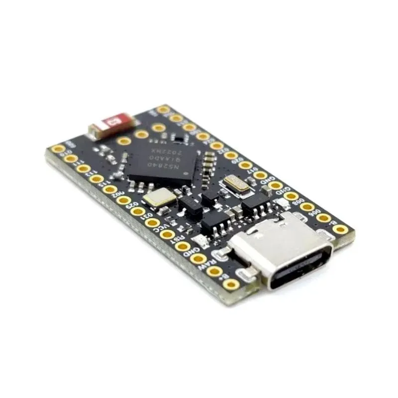
The NRF52840 Professional Micro is a wonderful alternative for constructing a Meshtastic LoRa Node. This compact board options:
- Built-in Battery Administration System (BMS)
- Bluetooth connectivity
- Very low energy consumption
- Small kind issue
This enables your node to run on a small battery for days. Nevertheless, it is vital to notice that the NRF52840 doesn’t have WiFi capabilities, so options just like the PAX counter or connecting to MQTT through WiFi will not be out there. This board is greatest fitted to purposes that depend on Bluetooth and LoRa communication.
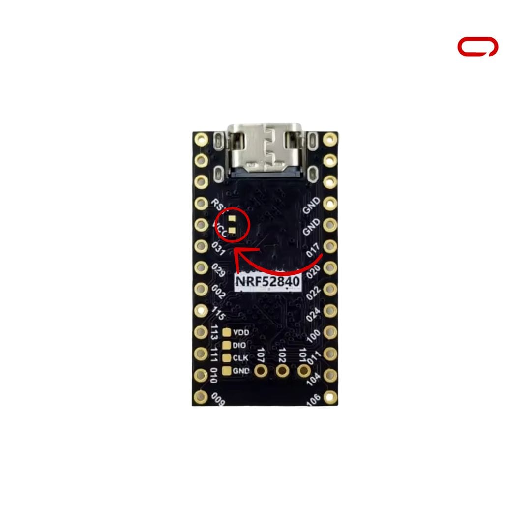
🔋
If you happen to plan to make use of a bigger battery, you have to quick the BOOST pads on the again of the board (positioned subsequent to RST and VCC).
Battery Cost Present: With out BOOST jumper: 100mA | With BOOST jumper: 300mA
HT-RA62 LoRa Module
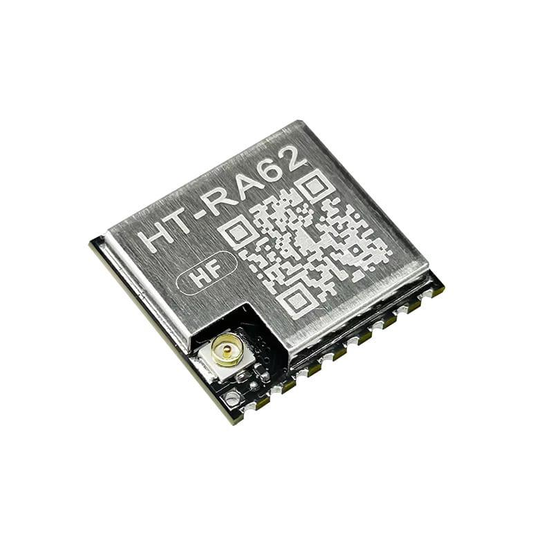
The HT-RA62 LoRa module is a compact, surface-mount (SMC) model of the favored LoRa radio, designed for integration into customized PCBs. Not like the RA-02 DIP model, which options through-hole pins and is appropriate for breadboarding and prototyping, the HT-RA62 requires extra superior soldering methods and exact handbook soldering. This trade-off, nonetheless, permits for a a lot slimmer and extra space-efficient design.
The module helps each 433 MHz and 868/915 MHz frequency bands, relying on the particular mannequin, providing flexibility for deployment throughout completely different areas in compliance with ISM band rules. Constructed on the Semtech SX1262 newer chipset (sometimes the SX1276 or SX1278), it delivers excessive sensitivity and long-range communication capabilities.
Meeting
Since we’re working with surface-mount elements, this meeting will probably be tougher than utilizing through-hole elements. Take your time and follow earlier than beginning if you happen to’re new to SMC soldering.
💡
Step 1: Put together the Professional Micro and PCB
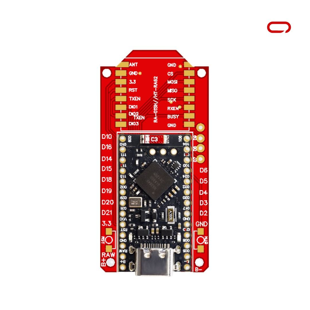
- Align the Professional Micro board with the holes on the PCB
- Make sure the USB port is going through outward, and the PCB is going through up
- You must see the Professional Micro on high with the PCB beneath, and above the Professional Micro, the 2 columns of 8 pads designated for the LoRa module
Step 2: Set up and Solder the Professional Micro
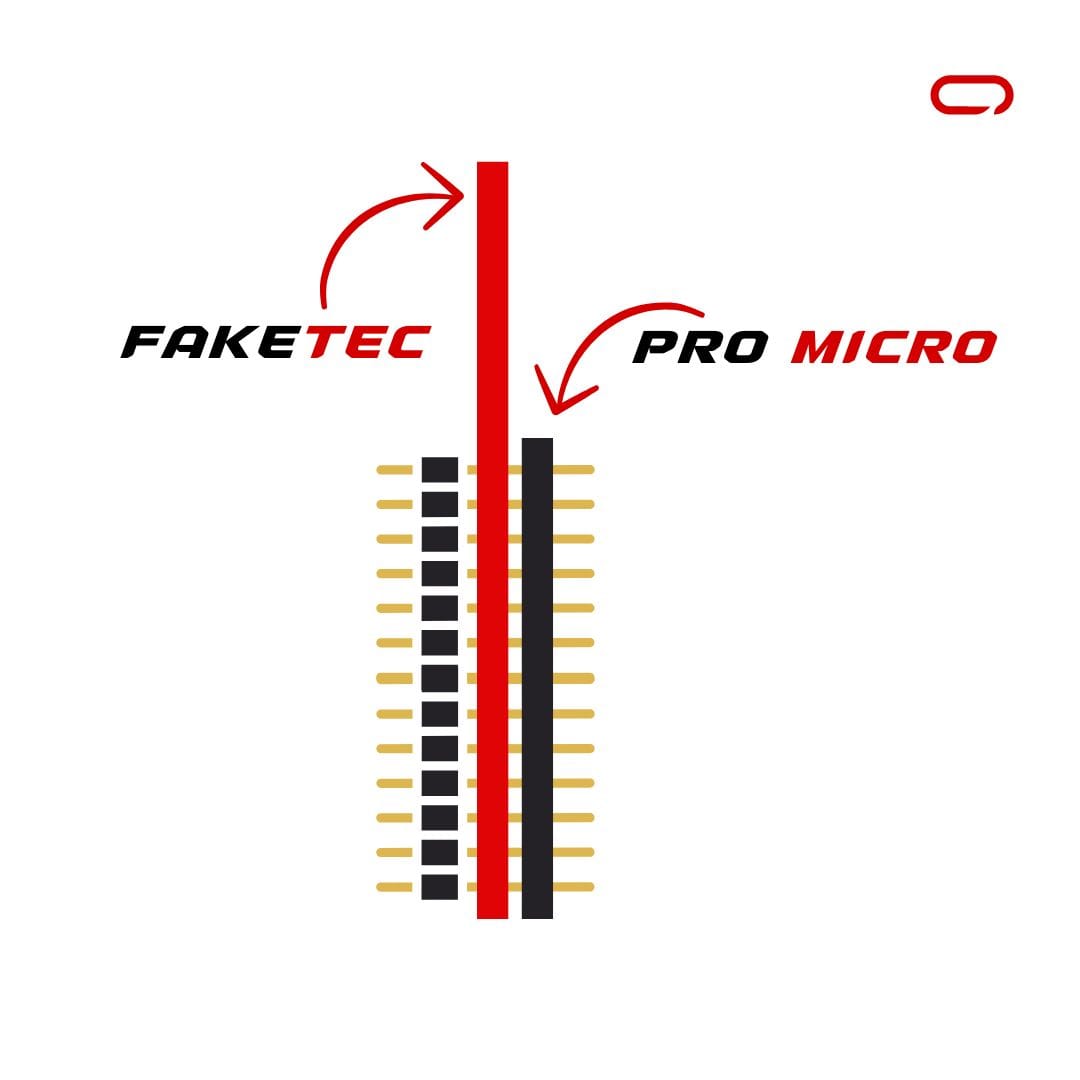
- Insert the header pins that got here with the Professional Micro from the underside of the PCB
- Push the pins by way of the PCB after which by way of the Professional Micro
- Place the complete meeting on a desk with the pins pointing up
- Use tape to safe it in place if wanted
- Start soldering the pins
- As soon as all pins are soldered from the highest, flip the board and break the black plastic holding the pins collectively utilizing a small cutter (like these that include 3D printers). Break it in chunks each 4 pins make a break. It should make it a lot simpler to take away it afterward.
- Fastidiously peel away the plastic with the cutter tip
- As soon as all pins are soldered from the highest and the plastic eliminated, solder from the underside facet for higher conductivity
- Utilizing wire cutters, trim the surplus pins that stick out
- Calm down the Professional Micro first, then plug it into an influence supply to check if it nonetheless works
⚠️
Put on eye safety! The reduce pins can fly off in all instructions.
Step 3: Solder the LoRa Module
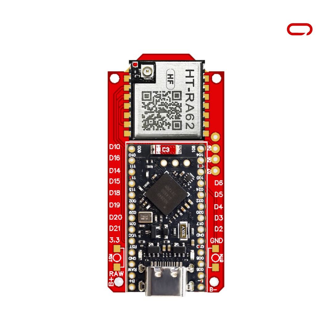
- Orient the LoRa module with the IPEX connector positioned on the high left nook
- Align it rigorously with the pads on the PCB
- Since there are not any pins to carry it in place, use electrical tape to safe it briefly. Professional tip: Stretching {the electrical} tape makes it narrower, which might help safe the module to the board
- Start by soldering one nook pad (GND or ANT is beneficial)
- As soon as the primary joint is full, the module ought to be steady sufficient to proceed soldering the remaining pads
- Take breaks as wanted and work rigorously – there is no rush!
💡
For SMC soldering, apply a small quantity of solder to the pad first, then maintain the element in place with tweezers whereas reheating the solder. This “tack soldering” strategy makes alignment a lot simpler.
⚠️
After finishing the wiring, it is essential to not overlook to attach your antenna
Flashing The Software program
Earlier than utilizing your Meshtastic node, you will have to flash it with the suitable firmware.
Step 1: Replace the Bootloader
Most NRF52840 Professional Micro boards include an outdated bootloader model that wants updating:
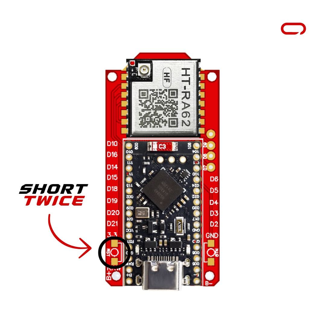
- Join the node to your PC utilizing an information cable
- Put the node into DFU (System Firmware Replace) mode by shorting the GND and Reset pins a couple of times
- A brand new drive ought to seem in your laptop
- Test the
INFO_UF2.TXTfile to find out your present bootloader model - Go to Adafruit’s GitHub page for nRF52 Bootloader releases
- Discover the following launch after your present model (you have to replace incrementally)
- Obtain the
nice_nano_bootloader-X.X.X.HEXandnice_nano_bootloader-X.X.X.UF2recordsdata to your board - Drag and drop the
.HEXfile onto the drive first, then the.UF2file - The system will disconnect and restart
- Test the bootloader model once more and repeat if crucial till you attain the newest model
Step 2: Set up Meshtastic Firmware
- Go to the Meshtastic net flasher
- Choose “NRF52 Professional-micro DIY variant” from the record
- Obtain the UF2 file
- Put your node in DFU mode once more
- Drag and drop the downloaded UF2 file onto the drive
- Look forward to the system to restart (this will likely take a minute or two)
Pairing Units
With the {hardware} assembled and the firmware flashed, you are now able to pair your FakeTec Meshtastic node together with your cellphone:
- Obtain the Meshtastic app in your cellphone (out there for each iOS and Android)
- Navigate to the Bluetooth web page and wait to your system to seem
- Choose your Meshtastic system from the record
- When prompted for a pairing PIN, enter “123456”
- Choose your area based mostly in your LoRa frequency (e.g., “EU433” for 433MHz modules)
- The node will restart, and you will be able to go!
Conclusion
Constructing your individual Meshtastic node with the FakeTec PCB design affords a superb stability of cost-effectiveness and performance. At roughly $11 for the essential elements, this DIY strategy makes mesh networking accessible to hobbyists and fanatics.
The meeting course of, whereas requiring some soldering talent, is easy when following the step-by-step directions. The NRF52840 Professional Micro’s built-in battery administration and Bluetooth capabilities, mixed with the compact HT-RA62 LoRa module, create a power-efficient node good for off-grid communication.