Dive into the thrilling world of FPV drones! Comply with our step-by-step information to assemble your individual drone. Our detailed step-by-step information walks you thru each a part of the method, from connecting the flight controller and motors to putting in the digital camera and receiver.
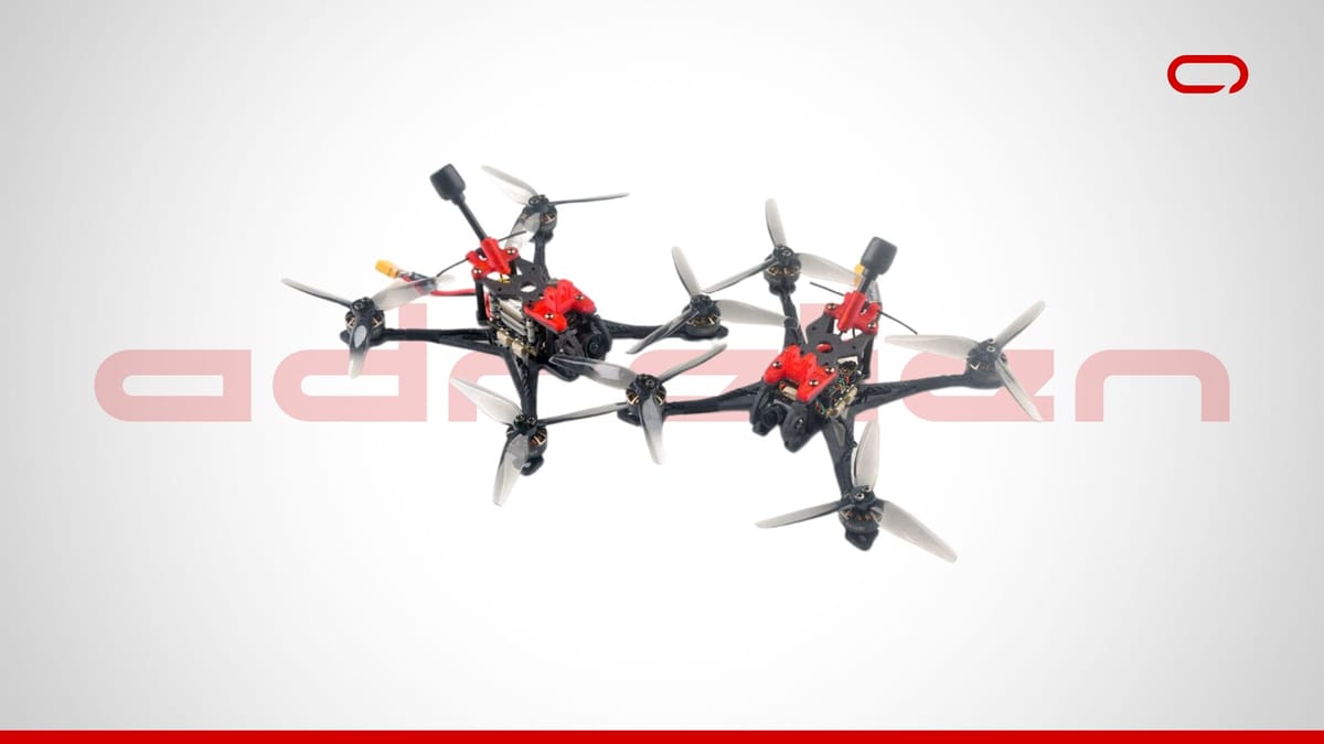
Constructing an FPV (First-Particular person View) drone is an thrilling and rewarding challenge that permits you to dive deep into the world of drones, electronics, and aviation. Whether or not you are a seasoned fanatic or a newcomer to the interest, assembling your individual drone supplies a hands-on expertise that enhances your understanding of how these drones work. On this complete information, we’ll stroll you thru the step-by-step technique of assembling an FPV drone.
We’ll be utilizing the next elements for this construct:
Instruments You Will Want
- Soldering iron and solder
- Hex keys (M2) and screwdrivers
- Electrical tape or warmth shrink tubing
- Zip ties
- Tweezers
- Double-sided tape or foam pads
Step 1: Making ready the Flight Controller (FC) and ESC Stack

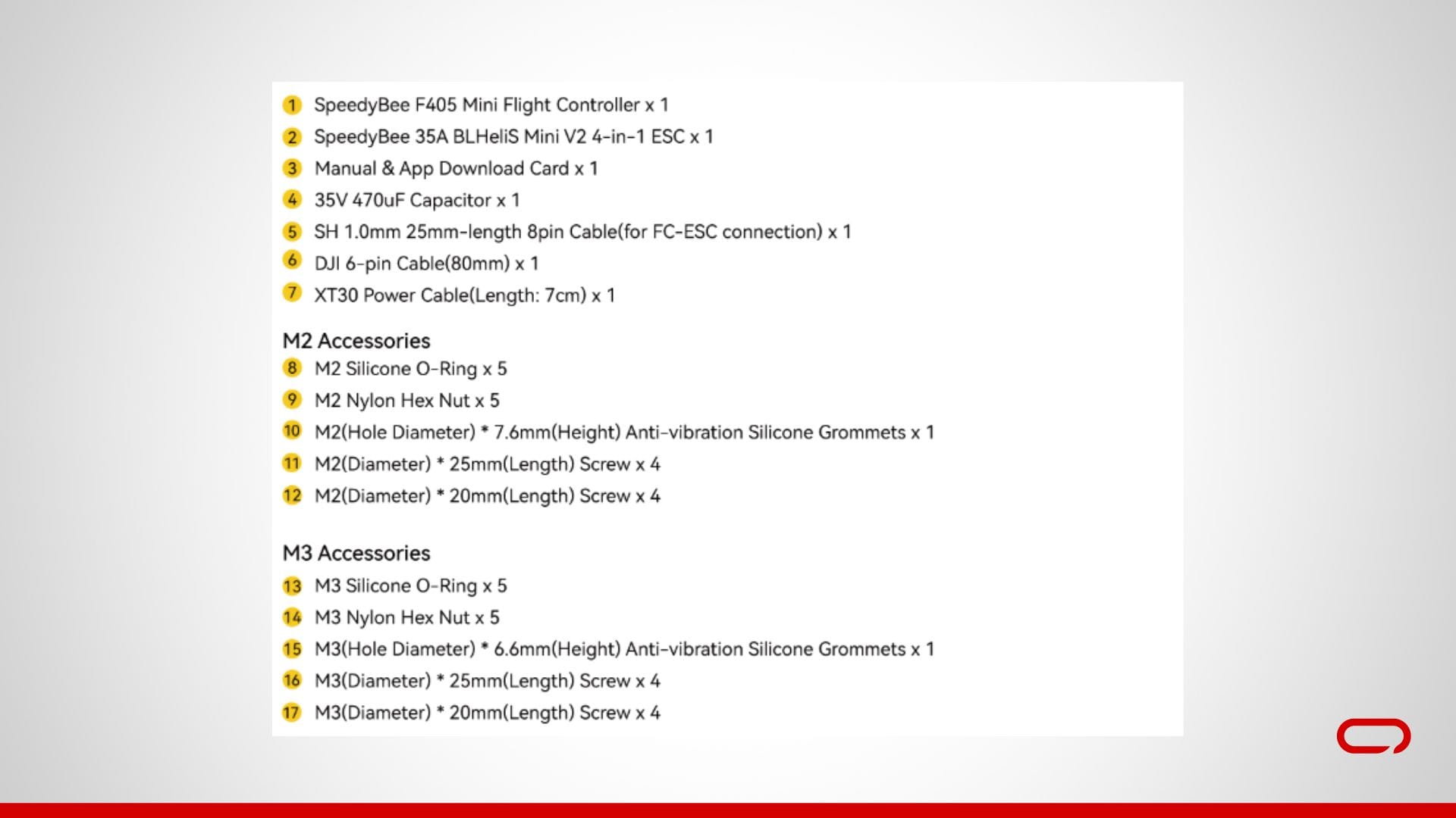
- Unbox the Stack: Begin by unboxing the SpeedyBee F405 Mini BLS 35A 20×20 Stack. Lay out all of the parts to make sure you have the whole lot you want.
- Put together the FC: Place the FC on a non-conductive floor. Guarantee you could have a transparent view of all of the pads.

Step 2: Putting in the FPV Digicam
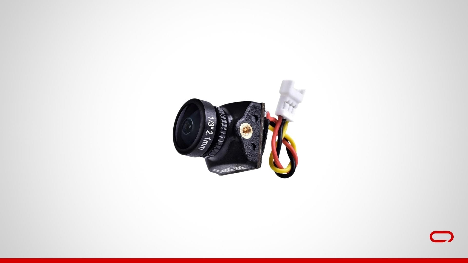
- Join the Digicam Wires: The RunCam Nano 2 FPV Digicam sometimes has three wires:
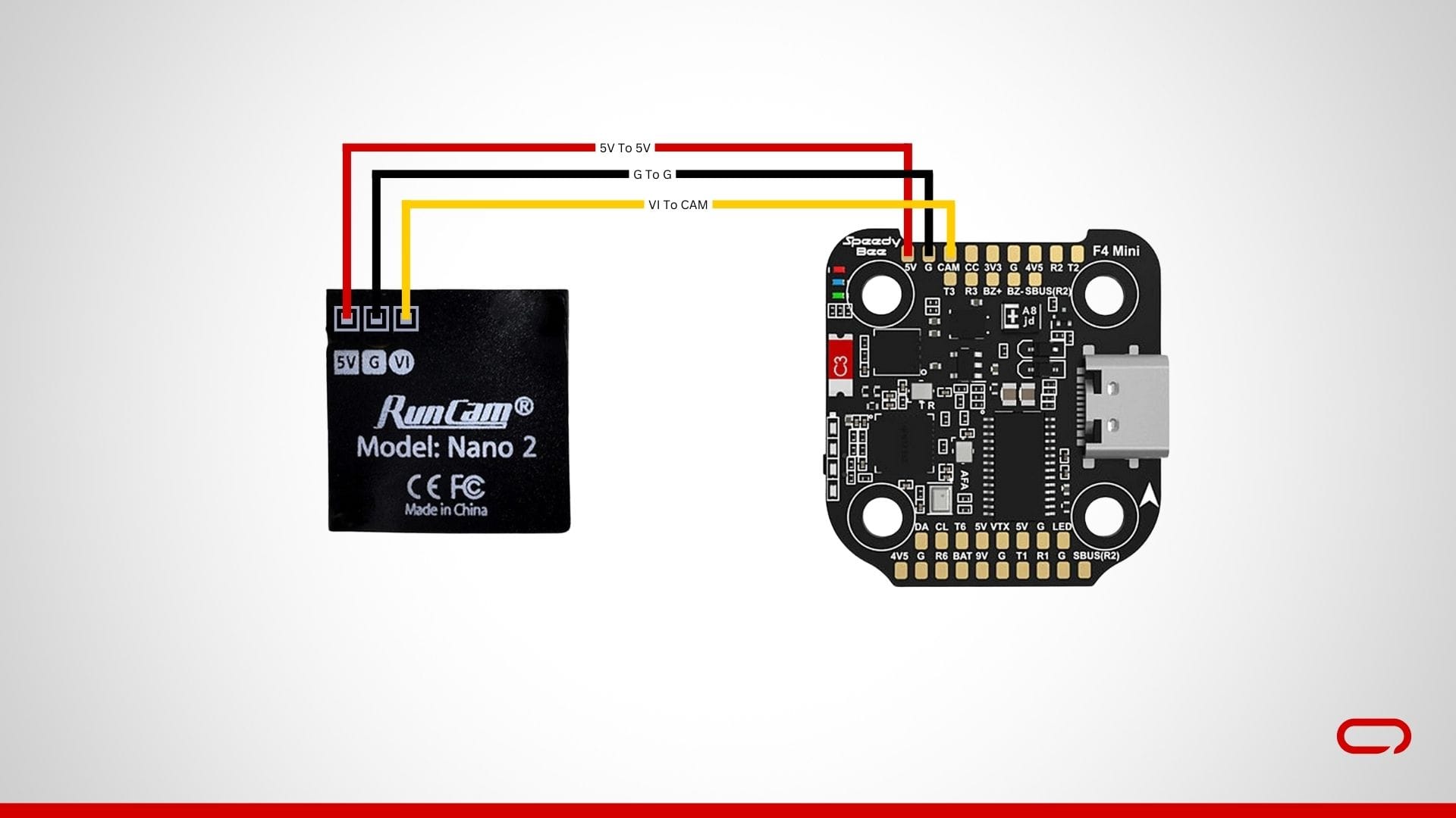
- Energy 5V (purple): Solder to a 5V pad on the flight controller.
- Floor (black): Solder to a GND pad on the flight controller.
- Video (yellow): Solder to the CAM pad on the flight controller.
💡
Safe the Digicam: Briefly safe the digital camera to keep away from pressure on the solder joints. You possibly can finalize the mounting later.
Step 3: Putting in the VTX

Join the VTX Wires: The RUSH TINY TANK Nano VTX sometimes has a number of wires:
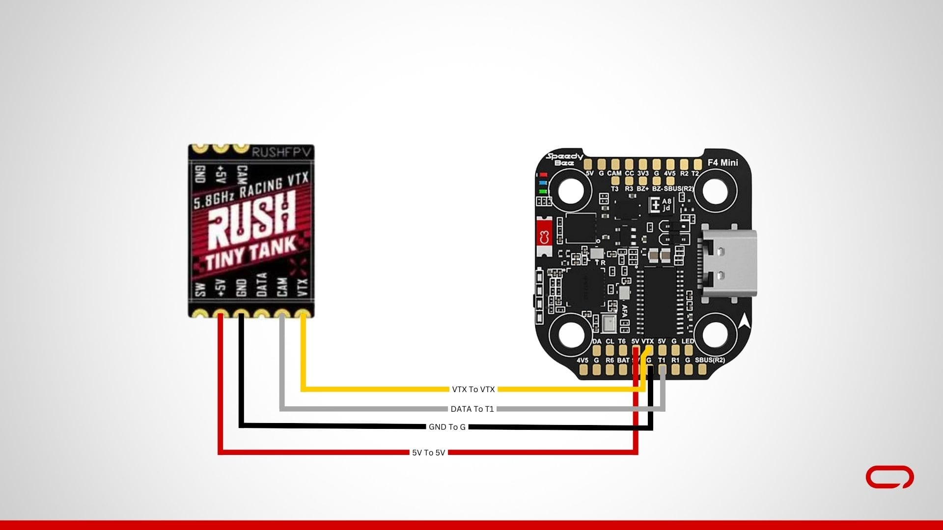
- Energy 5V (purple): Solder to a 5V pad on the flight controller.
- Floor (black): Solder to a GND pad on the flight controller.
- VTX (yellow): Solder to the VTX pad on the flight controller.
- Knowledge – SmartAudio (white): Solder to the T1 pad on a UART port on the flight controller for VTX management.
💡
After finishing the wiring, it is essential to not overlook connecting your antenna
💡
Safe the VTX: Briefly safe the VTX to keep away from pressure on the solder joints. You possibly can finalize the mounting later.
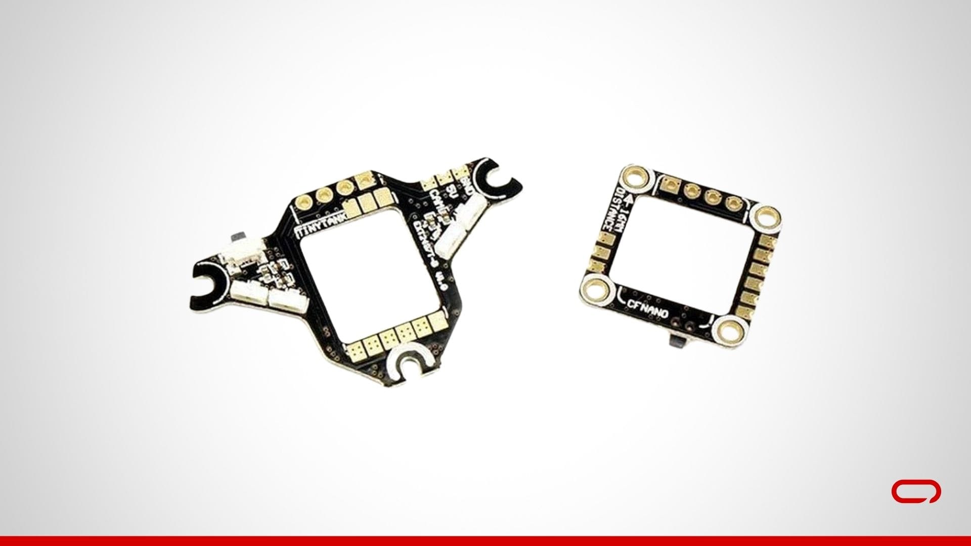
💡
You need to use the growth boards proven within the image above for simpler soldering with the VTX.
Step 4: Putting in the Receiver
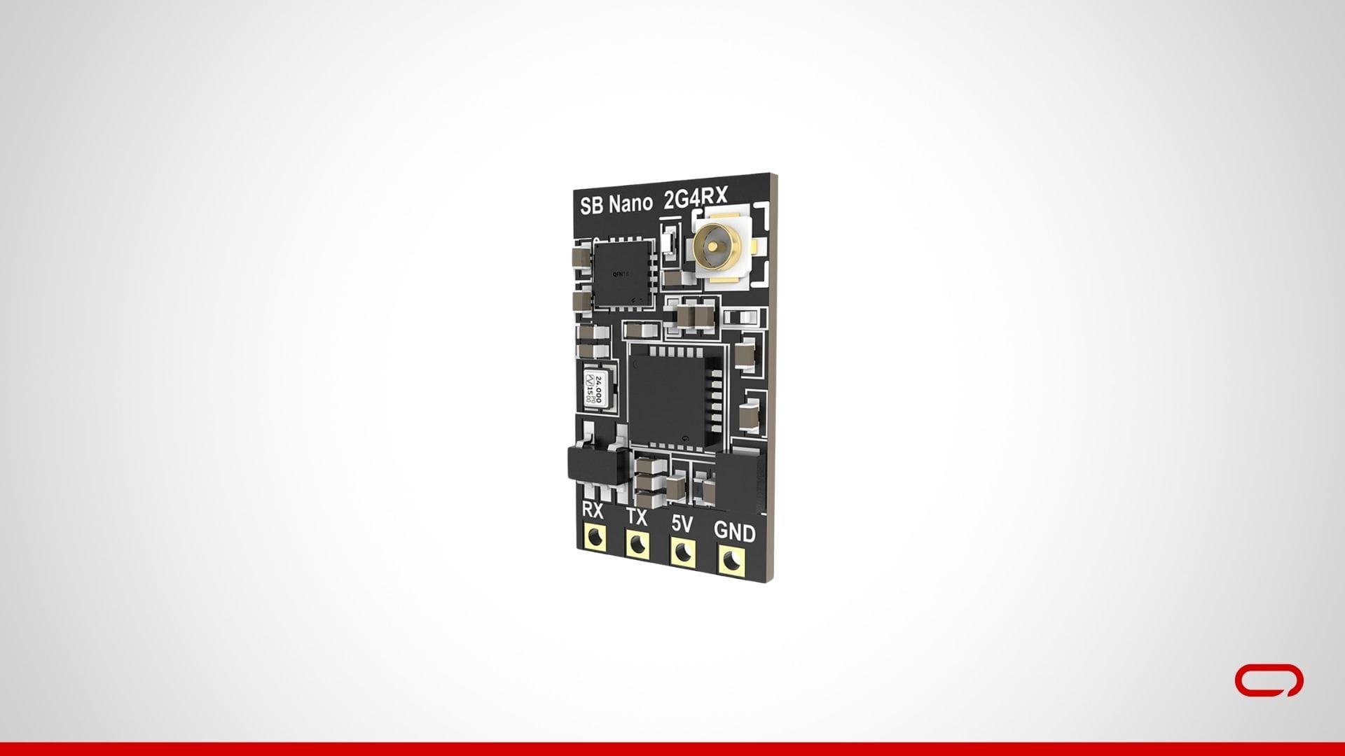
Join the Receiver Wires: The SpeedyBee Nano 2.4G ExpressLRS ELRS Receiver can have a number of wires:
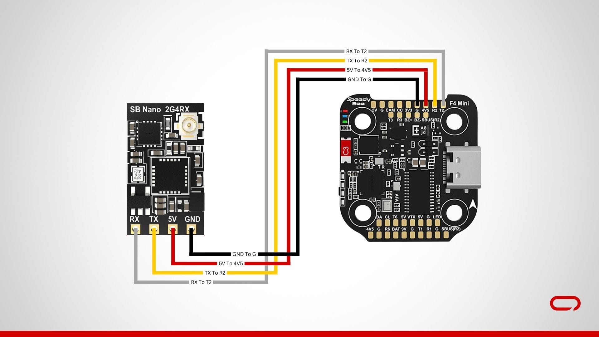
- Energy 5V (purple): Solder to a 5V pad on the flight controller.
- Floor (black): Solder to a GND pad on the flight controller.
- TX (yellow): Solder to the R2 pad on a UART port on the flight controller (sometimes UART2).
- RX (white): Solder to the T2 pad on a UART port on the flight controller (sometimes UART2).
💡
After finishing the wiring, it is essential to not overlook connecting your antenna
💡
Safe the Receiver: Briefly safe the receiver to keep away from pressure on the solder joints. You possibly can finalize the mounting later.
Step 5: Soldering the Battery Leads and Capacitor
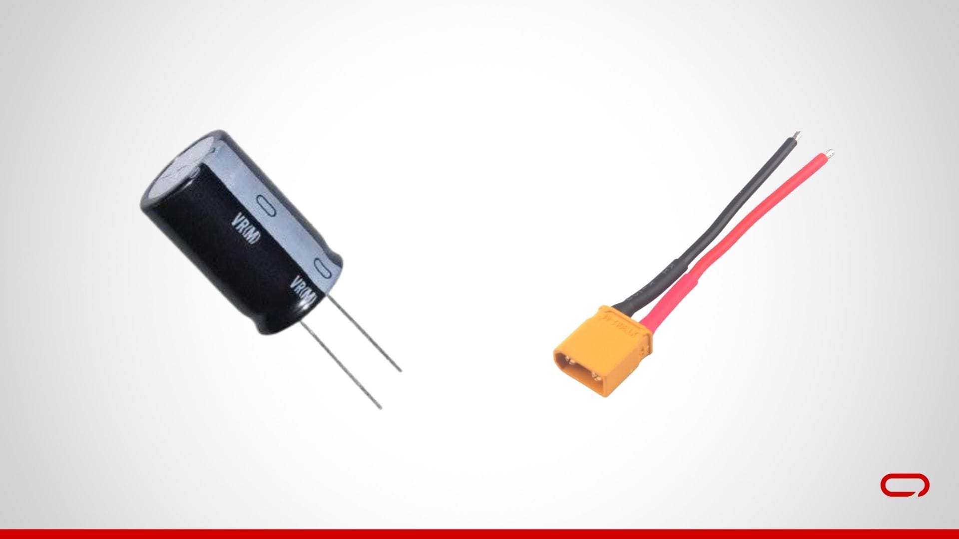
Put together the ESC: Place the ESC on a non-conductive floor. Guarantee you could have a transparent view of all of the pads.
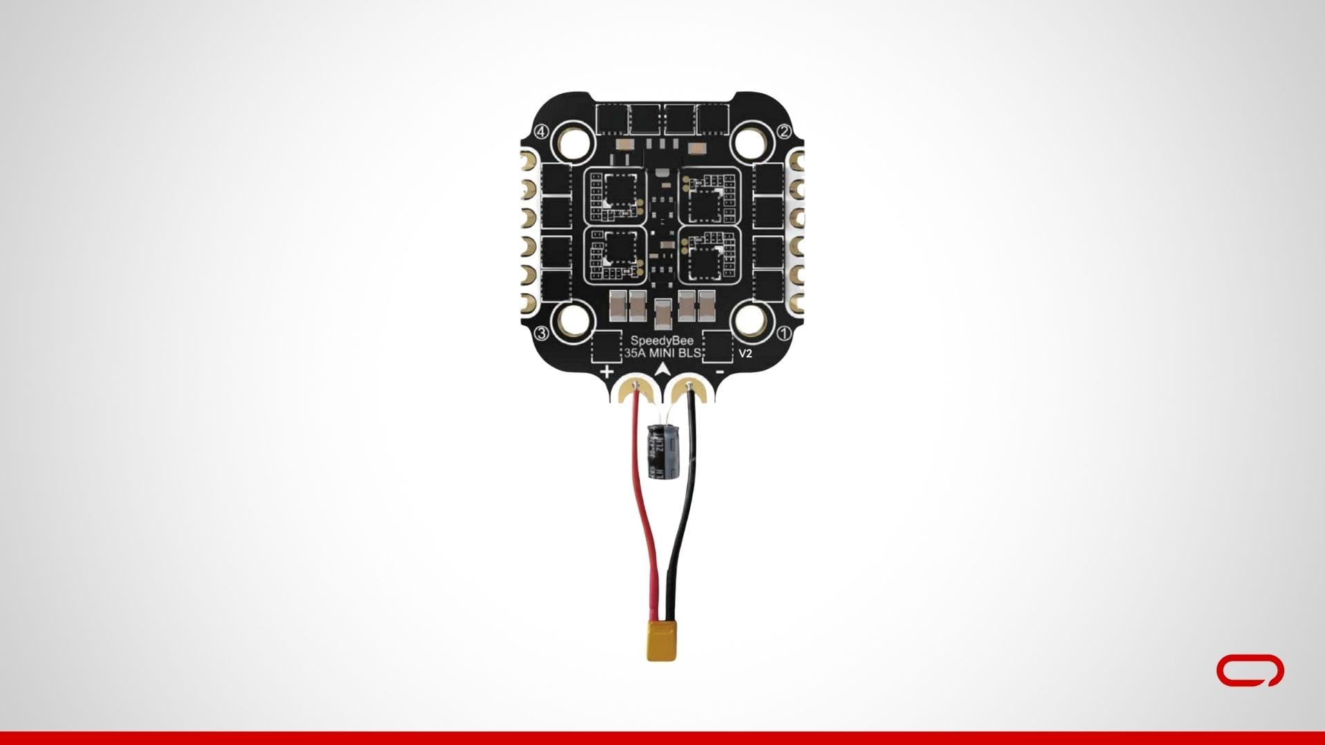
- Set up the Capacitor: Set up the capacitor via the holes throughout the + and – pads to assist filter out voltage spikes and noise.
- Solder the Battery Leads: Solder the battery results in the ESC pads. This entails connecting the constructive wire (purple) to the + pad and the detrimental wire (black) to the – pad. Use the next temperature and quantity of solder to make sure a robust connection.
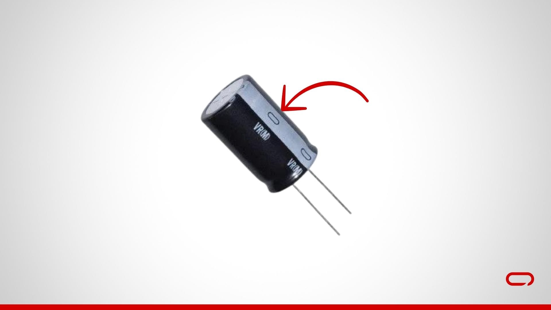
💡
Watch out of the capacitor polarity. You possibly can determine the detrimental aspect by the “-” image marked on the aspect of the capacitor
Step 6: Soldering the Motors to the ESC
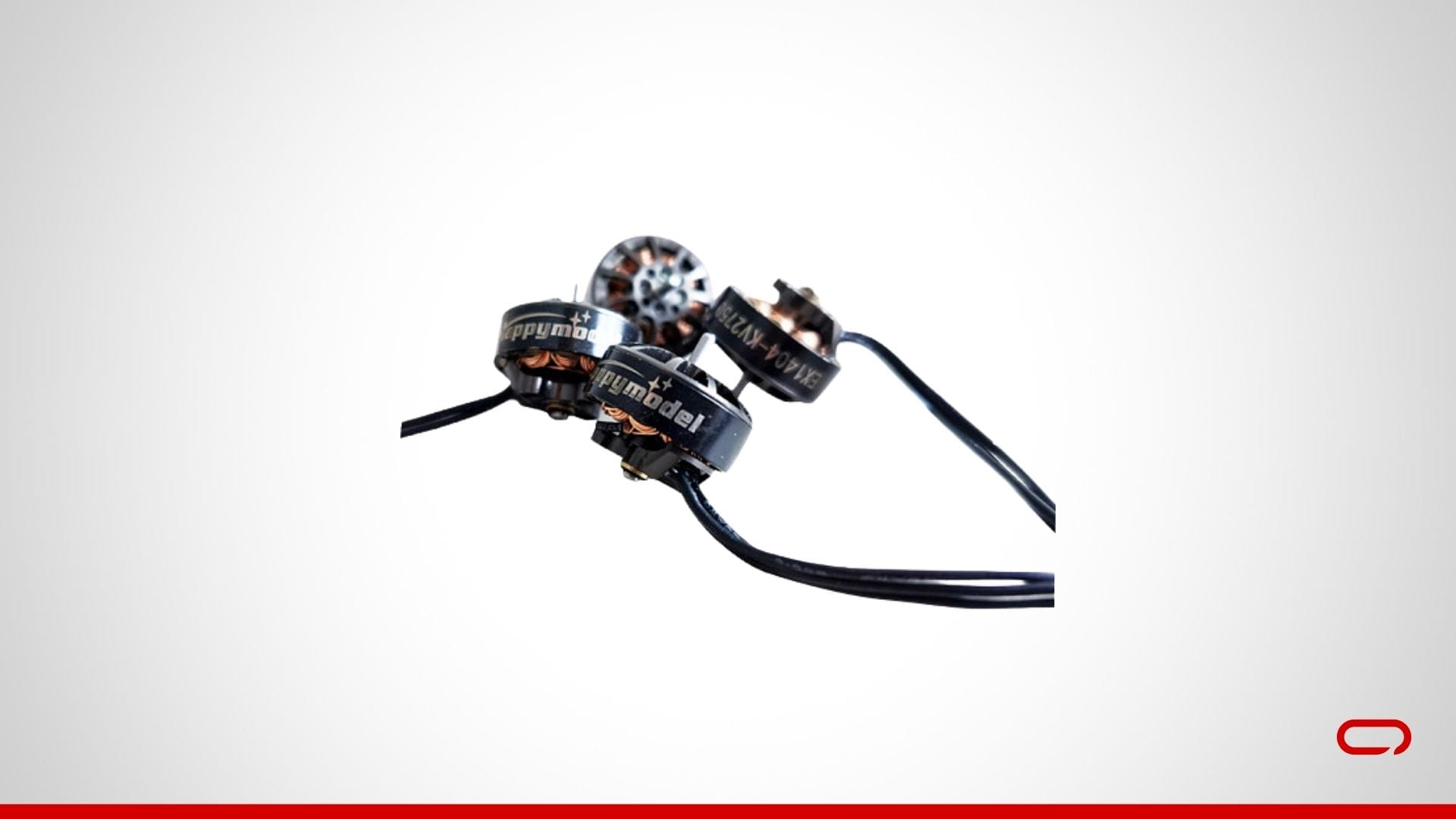
Join the Motors to the ESC: Solder the motor wires to the ESC pads on the flight controller board. Every motor can have three wires that should be related to the corresponding pads on the ESC:
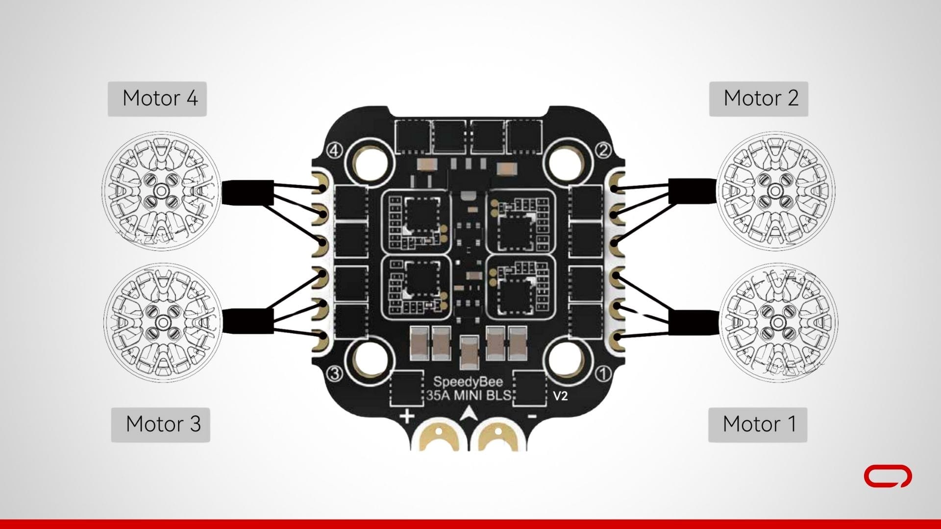
- Motor 1: Hook up with M1 pads.
- Motor 2: Hook up with M2 pads.
- Motor 3: Hook up with M3 pads.
- Motor 4: Hook up with M4 pads.
💡
Safe the Motors: Briefly safe the motors to keep away from pressure on the solder joints. You possibly can finalize the mounting later.
Step 7: Assembling Elements to the Body

- Unbox the Body: Begin by unboxing the HappyModel Crux35 3.5 Inch Body. Lay out all of the parts to make sure you have the whole lot you want. First, run the battery strap via the backplate.
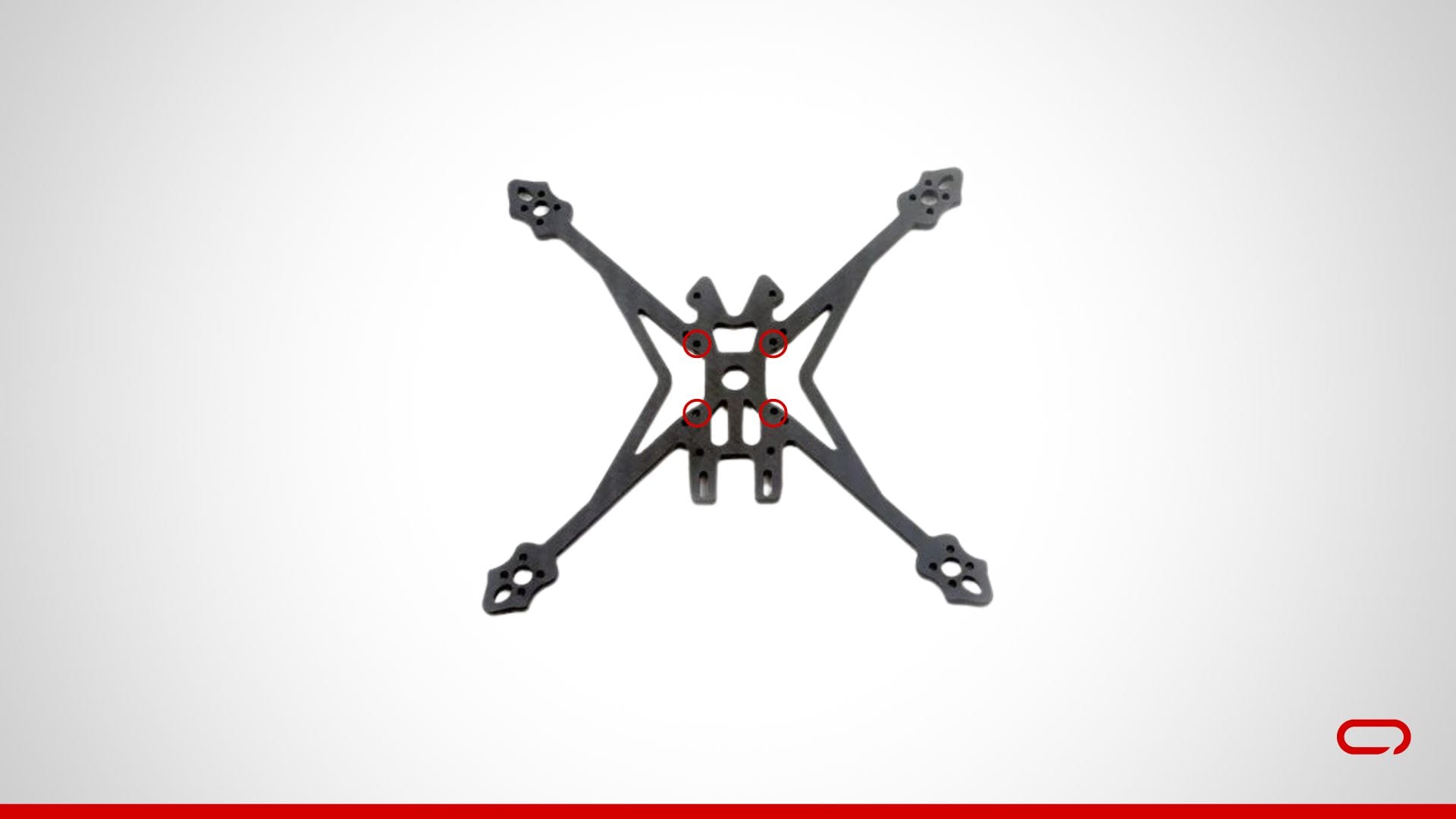
- Set up the ESC: Use the M2 screws offered, guaranteeing they’re of the suitable size. Place the ESC within the heart of the body and run the M2 screws via the holes within the heart of the body. Make sure the arrow on each the FC and ESC is going through up and ahead, in the direction of the digital camera. This orientation is essential for correct functioning.
- Add the Flight Controller (FC): Place the FC on high of the ESC, aligning the mounting holes. Safe the FC with the offered nuts. Tighten the nuts so they’re cosy however not overly tight. Make sure the arrow on each the FC and ESC is going through up and ahead, in the direction of the digital camera. This orientation is essential for correct functioning.
- Mount the Motors: Connect the Happymodel EX1404 motors to the designated motor mounts on the body utilizing the offered screws. Make sure that the motors are securely mounted.
- Set up the FPV Digicam: Take the digital camera bracket and use the M2 screws offered to mount the digital camera securely within the bracket. Connect the bracket to the designated spot on the body on the entrance.
- Set up the VTX: The VTX will be mounted on the highest plate of the body. Use M2 screws, zip ties, or double-sided tape to safe the VTX in place.
- Set up the Receiver: Mount the receiver behind the drone. Use zip ties or double-sided tape to safe the receiver. Slip the antenna via the TPU half vertically for optimum sign reception.
💡
The location of sure parts is basically based mostly on private choice and aesthetics. Be at liberty to regulate their places or search inspiration from on-line sources. Usually, the VTX and receiver are mounted on the again to reap the benefits of the TPU antenna holder, particularly if you’re utilizing a customized antenna.

Step 8: Assembling the Body
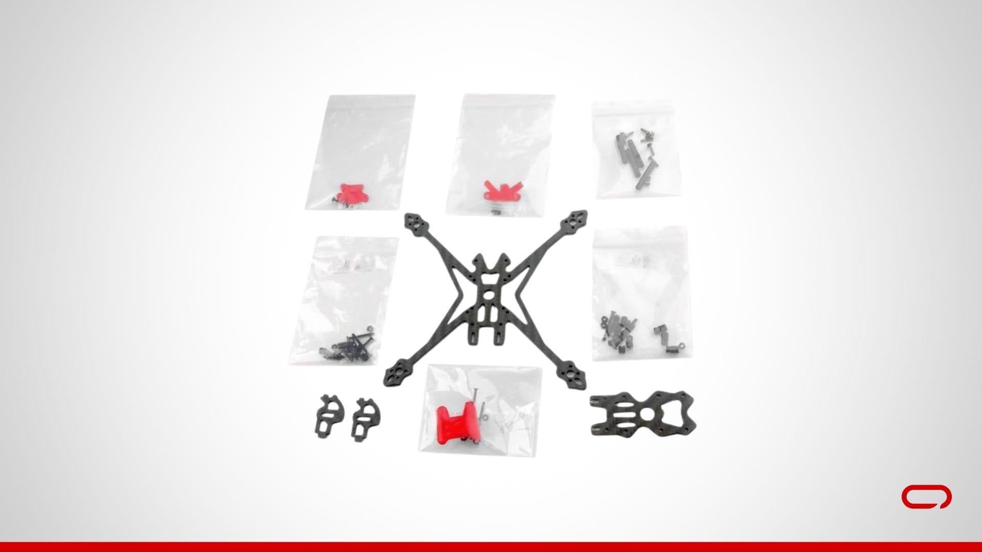
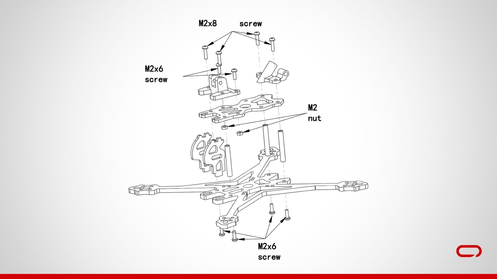
- Add the Spacers: Insert the spacers into the designated slots on the body. Safe the spacers with the offered M2x6 screws.
- Connect the TPU Elements: Place the TPU elements of their designated places on the highest plate. Safe the TPU elements utilizing the M2x6 screws and the M2 nuts offered.
- Set up the High Plate: Place the highest plate on the spacers. Use the M2x8 screws offered to safe the highest plate to the spacers, guaranteeing it’s tightly fitted.
- Set up the Battery Pad: Apply the battery pad sticker on the backside of the drone.
💡
Consult with the diagram beneath for detailed placement of every element and guarantee all elements are appropriately positioned and securely mounted.
Step 9: Bench Testing
- Preliminary Energy Test: Join the battery and energy up your drone utilizing the smoke stopper with out propellers. Make sure that all parts energy on appropriately.
- Test Motor Path: Use Betaflight to verify the motor instructions. Make sure that every motor spins within the right course. If a motor is spinning within the mistaken course, you’ll be able to reverse it in Betaflight.
- Set your UART: In Betaflight, navigate to the Ports tab. Set the peripherals for UART1 to VTX (TBS SmartAudio) and Allow Serial RX for UART2.
- Apply Presets: Within the Presets tab of Betaflight, seek for “Rush Tiny Tank.” Click on on it, choose “Rush Tiny Tank” from the dropdown listing, after which apply the preset. Do the identical for ExpressLRS 250Hz or 500Hz, relying in your transmitter (controller) settings.
- Confirm Digicam and VTX: Make sure that the digital camera feed is being transmitted appropriately and that the VTX is about to the right channel and energy stage.
- Receiver Binding: Bind your transmitter (controller) to the SpeedyBee Nano 2.4G ExpressLRS ELRS Receiver in response to the producer’s directions. Confirm that every one controls are working appropriately.
Step 10: Propellers and Last Checks
- Connect the Propellers: Safe the propellers to the motors. Make sure that the propellers are oriented appropriately in response to the motor rotation course (clockwise or counterclockwise).
- Last Test: Double-check all connections, screws, and settings. Make sure that the whole lot is safe and that there aren’t any unfastened wires.
Step 11: Check Flight
- Security Test: Earlier than the primary flight, double-check all screws, connections, and settings.
- Energy Up: Join the battery and energy up your drone with out the smoke stopper. Make sure that all parts are working appropriately.
- Maiden Flight: Carry out a maiden flight in a protected, open space. Begin with light maneuvers to make sure the whole lot is functioning correctly.
Conclusion
Congratulations! You’ve got efficiently assembled your FPV drone. Constructing your individual drone could be a complicated but extremely rewarding expertise, offering you with a deeper understanding of how drones work and the satisfaction of flying one thing you’ve got created your self. Take pleasure in your flights and all the time prioritize security. Glad flying!
Be at liberty to succeed in out within the feedback when you have any questions or want additional help.


